Automated Basil Farm
Growing plants can be challenging for people who don’t always have the time to take care of them. This is certainly true for me. I have tried many times to grow basil indoors. However, with school and other life activities going on, I always managed to kill the plant before it was able to grow enough basil to make pesto out of. This is not just due to forgetting to water it; basil also requires quite a bit of sun light. This makes it difficult to grow it in the winter, and even in the summer in Oregon.
I wanted to make an automated herb garden that would water itself based on moisture content of the soil. Sunlight also needed to be supplied by a full spectrum bulb that would be left on during the day, and off during the night to simulate the day-night cycle.
Exact numbers for how much light and/or water a specific plant requires is hard to find and will vary a lot based on the size of plant, and other environmental factors. Therefore, these variables would need to adjusted. To do so, the device logged data, informing the user how much water and daylight the plant has received. The user could then gauge how well the plant was doing and adjust variables from there to ensure the plant is getting the optimum level of resources.
A more practical approach might have been to simply forego the sensors, and just adjust the water levels manually. It really comes down to if you are simply trying to grow basil, or you are trying to make cool graphs. For me, I am mostly trying to make cool graphs.
Sensors
A flow meter and a moisture sensor were used in this project. The moisture sensor ran on 12V and output 0-3V based on the volumetric moisture content (VMC) of the soil it was inserted into.
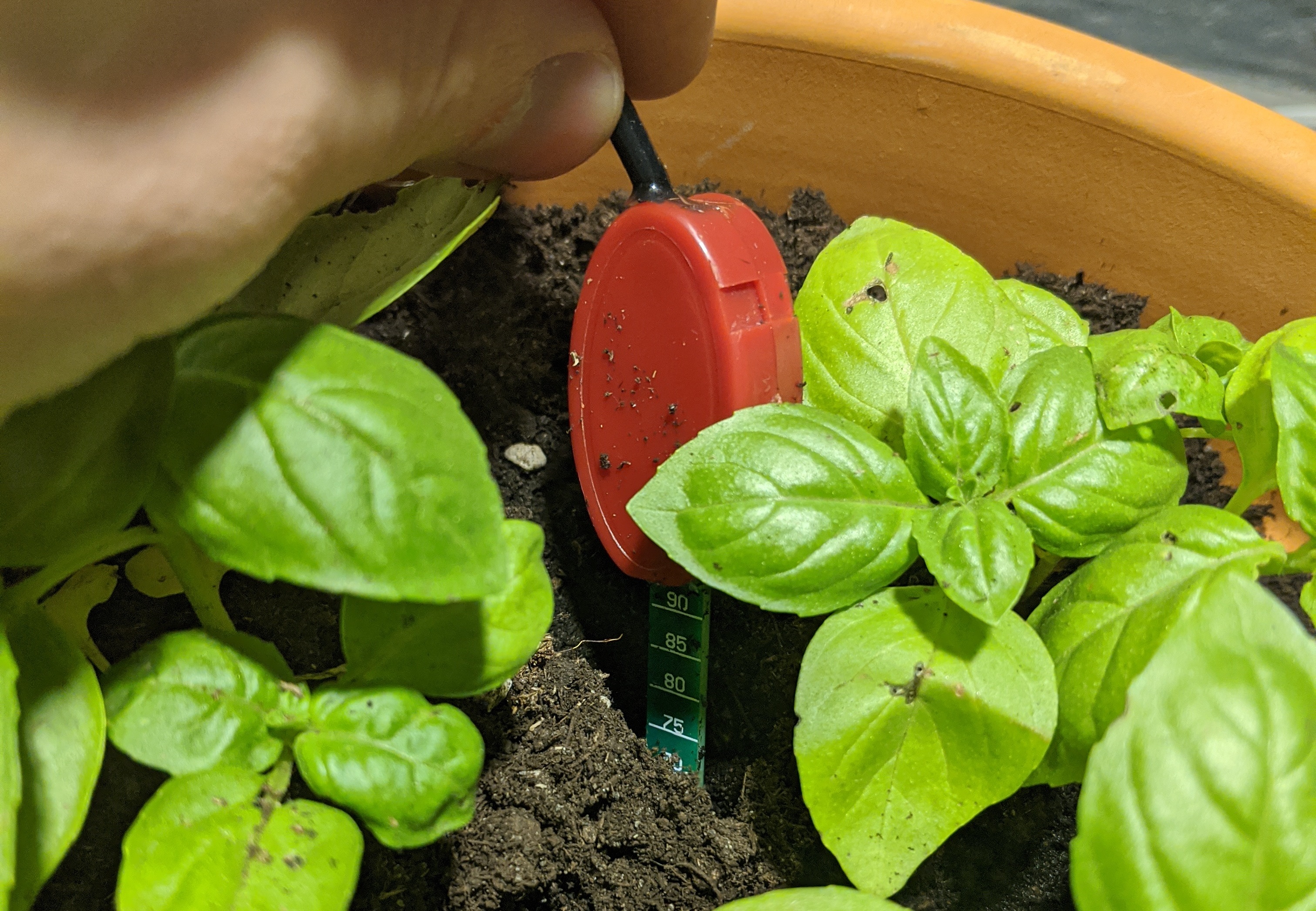
The output was measured using the ADC on the microcontroller. The senor was able to detect a VMC between 0 and 50\%. This data was logged with time to monitor the state of the basil farm.
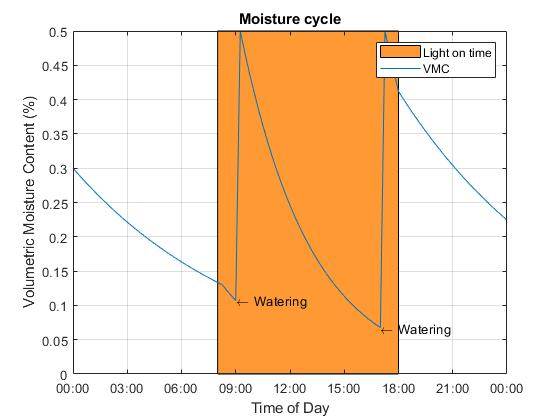
I imagined that the moisture cycle would look something like the image below. The orange space represents time at which light is on. The spikes in the water content are observed from the watering times.
A hall-effect flowmeter was installed to provide feedback for how much water was being supplied to the farm. This signal was read using a pull-up resistor, and a hardware interrupt on the micro controller searching for a falling edge to measure pulses. This helped provide consistent watering to the farm.
Actuators
The farm used two actuators, a full spectrum light to provide indoor sunlight, and a solenoid valve to control the flow of water to the plants.
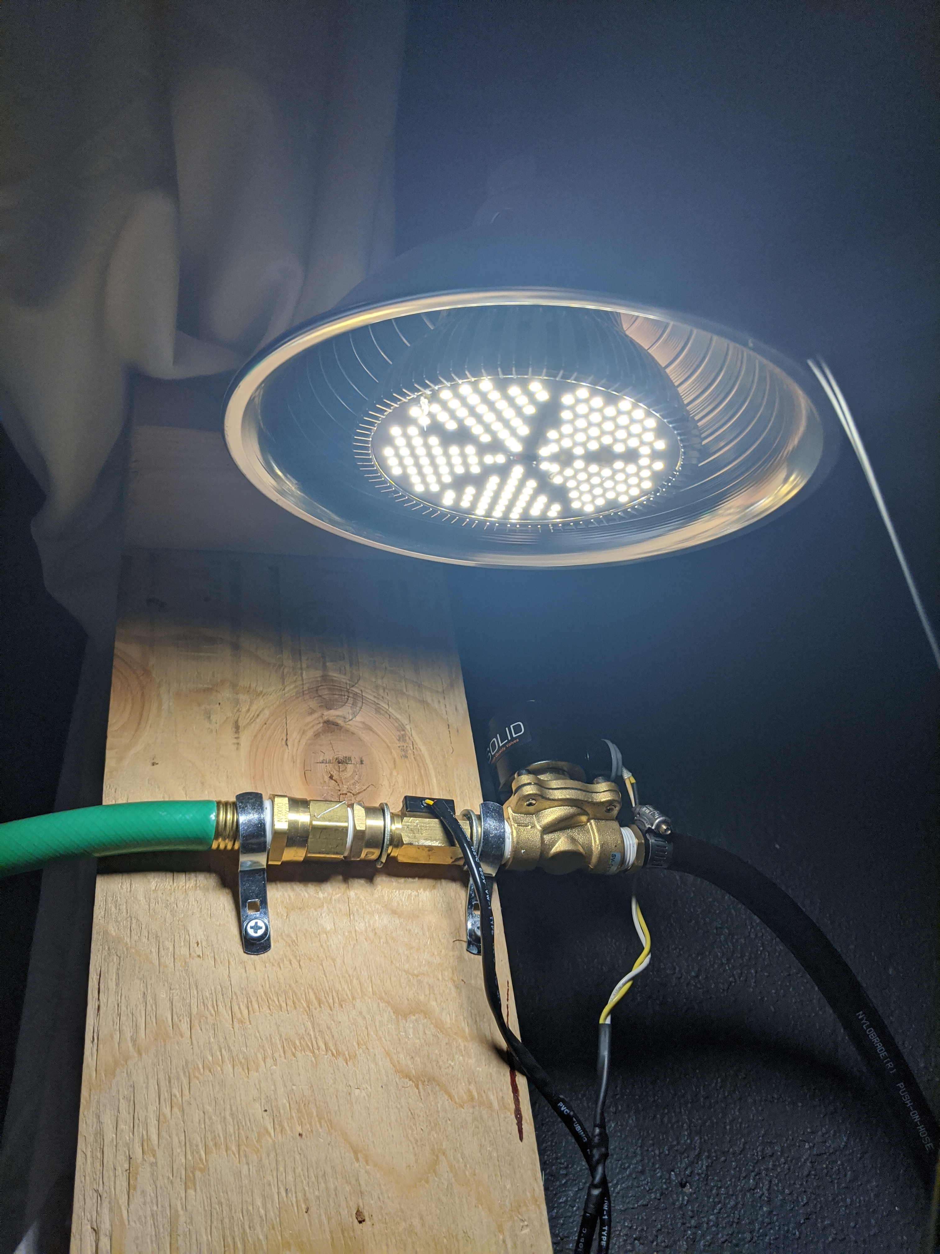
The lamp ran on 120VAC, so this needed to be controlled with a relay. It would have been interesting to implement dimming; however, the full spectrum LED bulbs are non-dimmable. This can be circumvented using a PWM setup, however this would be difficult with a mechanical relay. The light was set to come on at 8am and turn off at 6pm.
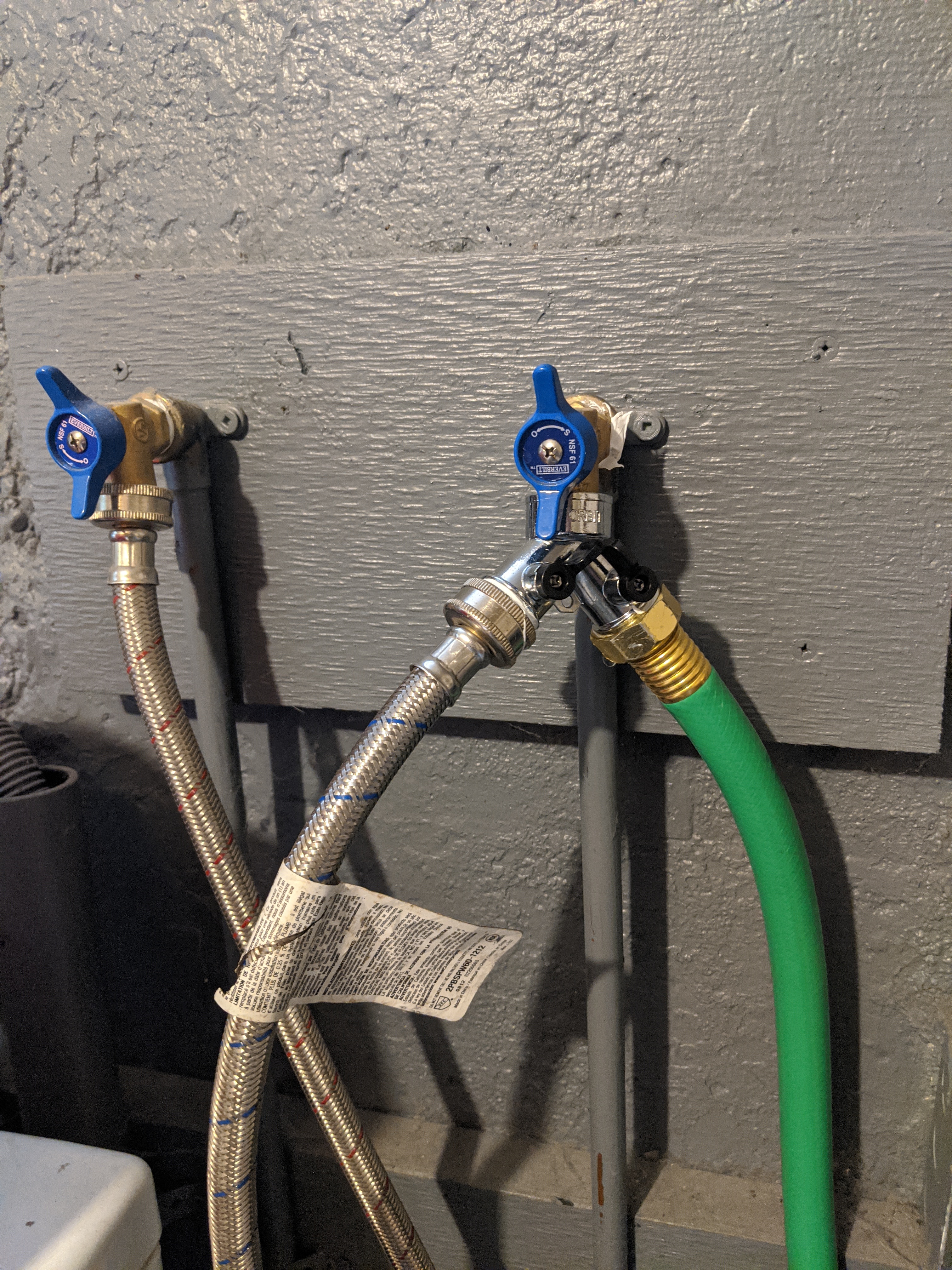
The solenoid valve also ran on 120VAC and used a relay as well. The relay control circuit was simplified using a ULN2003 Darlington transistor array with built in flyback diodes. This enabled the microcontroller to control the relays using the digital outputs. The valve received 60 psi tap water from a hose T’ed off from my basement washing machine’s water supply.
The valve then connected to a small hose that fed into the farm. One issue I encountered with this setup is how 60 psi water flowing directly out of a hose onto a plant is far too forceful. It also only waters one spot. One solution to this might be to use a shower nozzle or to use a soaker hose.
The flowmeter was placed before the valve to ensure that the sensor was always full of water. If the orifice of the sensor is not completely filled while water is flowing, it can lead to inaccuracies in the flow reading. The farm was watered at 9am and 4pm. The valve turns off when a certain number of pulses from the flowmeter are counted, telling the microcontroller to shut the valve. In case the flowmeter was to fail, a three second timeout was implemented to prevent catastrophic flooding. My roommates requested this feature.
Circuit
The system runs on 120VAC. It has a built in 12VDC power supply to run the microcontroller, sensors, and relays. The moisture sensor's signal is slightly below the logic level of the microcontroller so the output can be read directly from the ADC. The flowmeter's pulse signal is connected to a 3.3V pullup resistor which connects to an interrupt pin. The microcontroller controls the transistor array that drives the relays. A 1mF decoupling capacitor is placed next to the relays to smooth the 12V power.
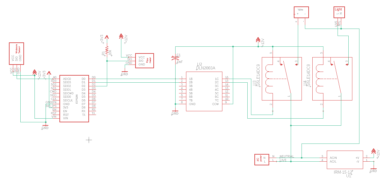
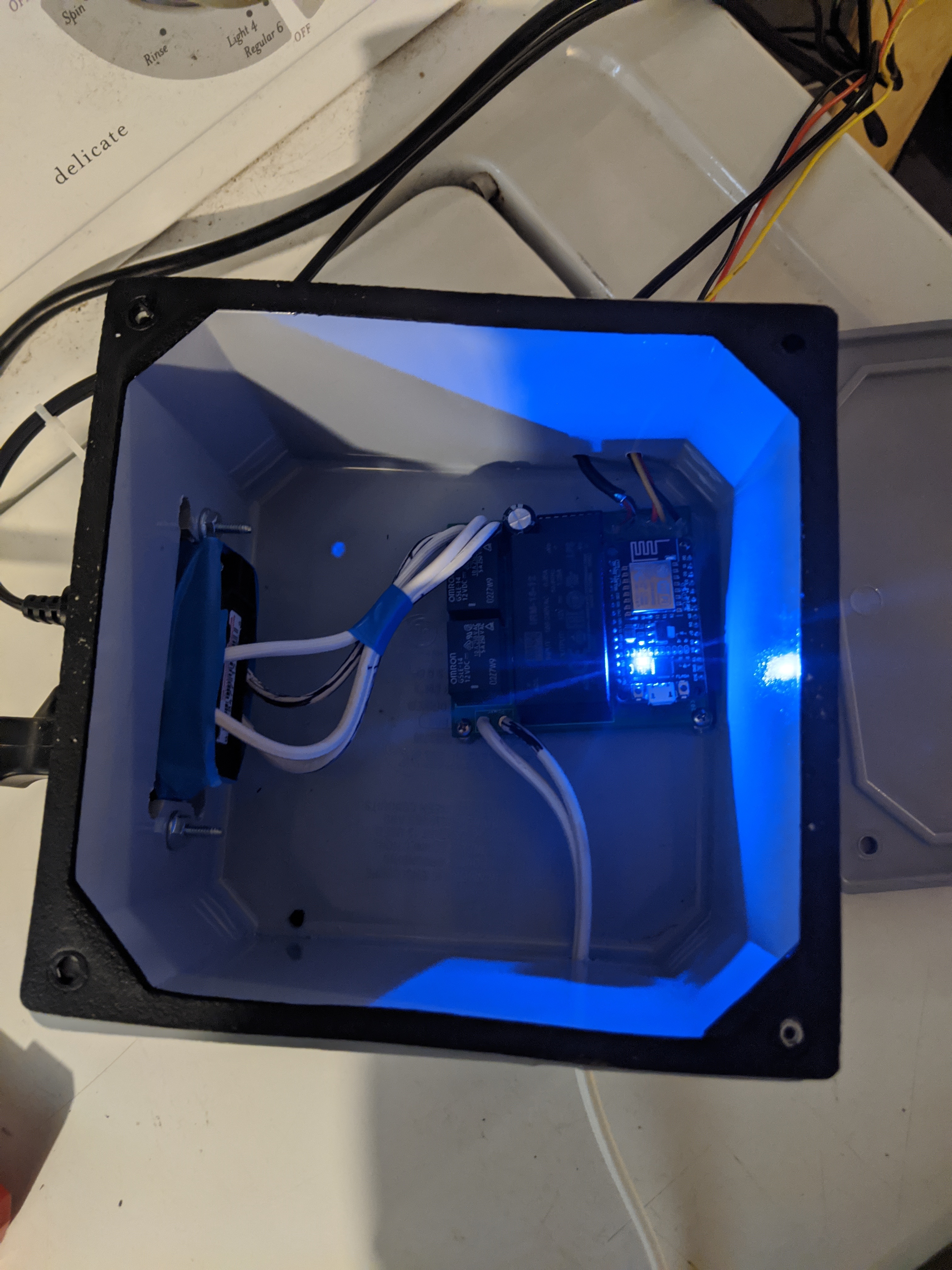
I placed the board inside of a junction box to protect people from the high voltage.
Software
The hardware was controlled using an ESP8266. The microcontroller can connect to the internet over WiFi. This enabled the system to sync to internet time using NTP. It also enabled wireless data logging on the raspberry pi zero. The pi ran an MQTT broker which the ESP8266 posted to.
A python script running on the pi ran Paho to subscribe to the MQTT broker and log the incoming data from the ESP8266 to a text file. A new text file was generated every day, and the scripts could be imported into Matlab to plot. Timing for the moisture sensor is not critical. Therefore, moisture readings were polled, and the sample rate was slow. To avoid enormous file sizes, the sensor sampled at 0.5 Hz.
Results
The sensors and actuators worked well. The image below shows the moisture plotted throughout the day. The orange region is the time that the lamp is on.
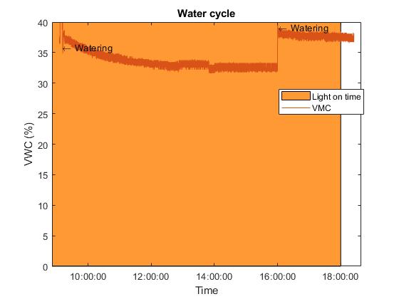
I was happy with the data I was able to gather. However what I noticed from that is how the soil appeared to dry very slowly in my dingy college basement.
The part of this project that could use some improvement is the farm itself. A nozzle could be used to water the plants more gently and evenly. Additionally, my basement was cold and humid. I think this setup would work much better in a greenhouse where the environment could be regulated better.