ESRA Project Overview
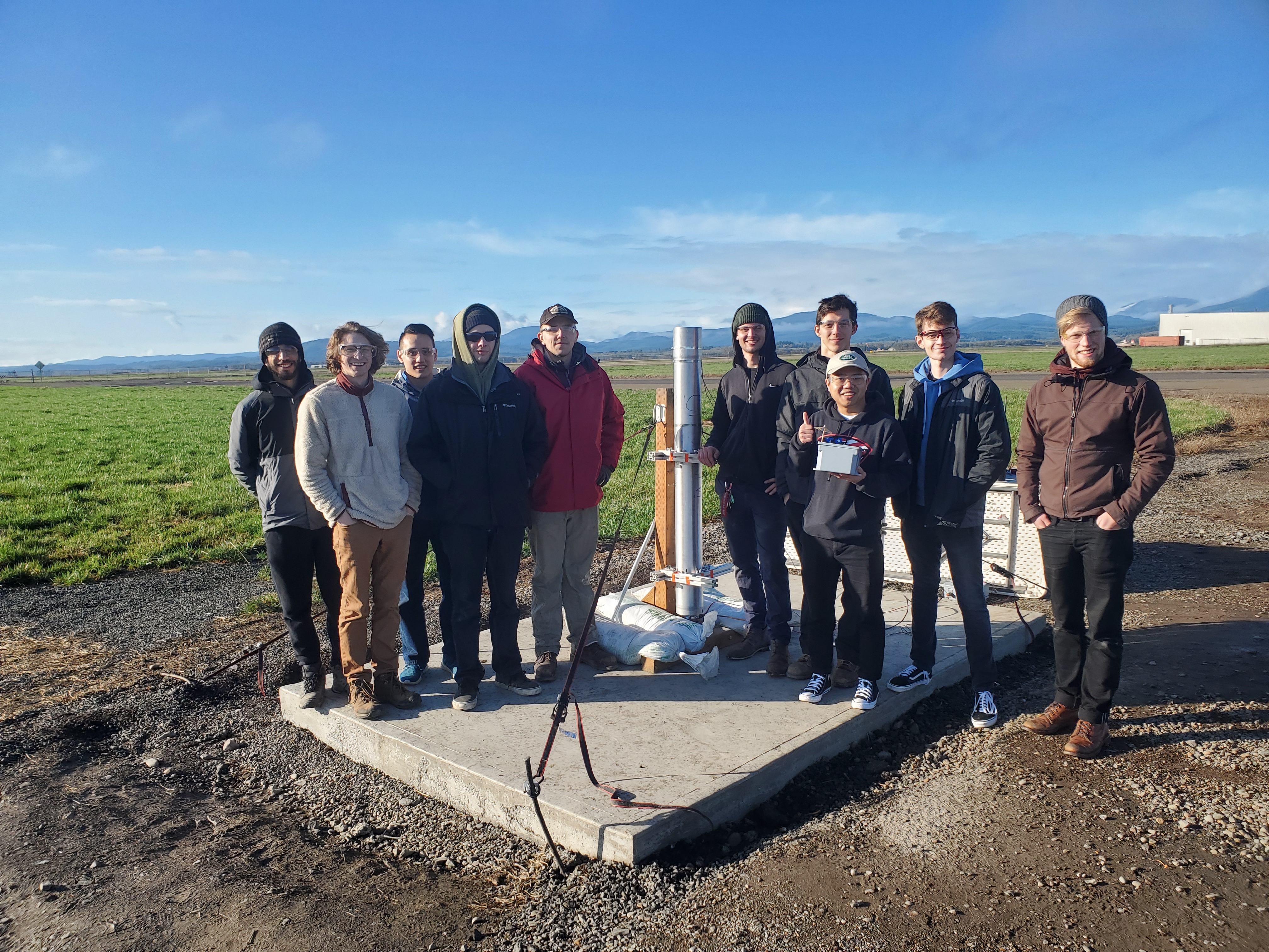
OSU AIAA ESRA 2019-2020 Rocketry Team
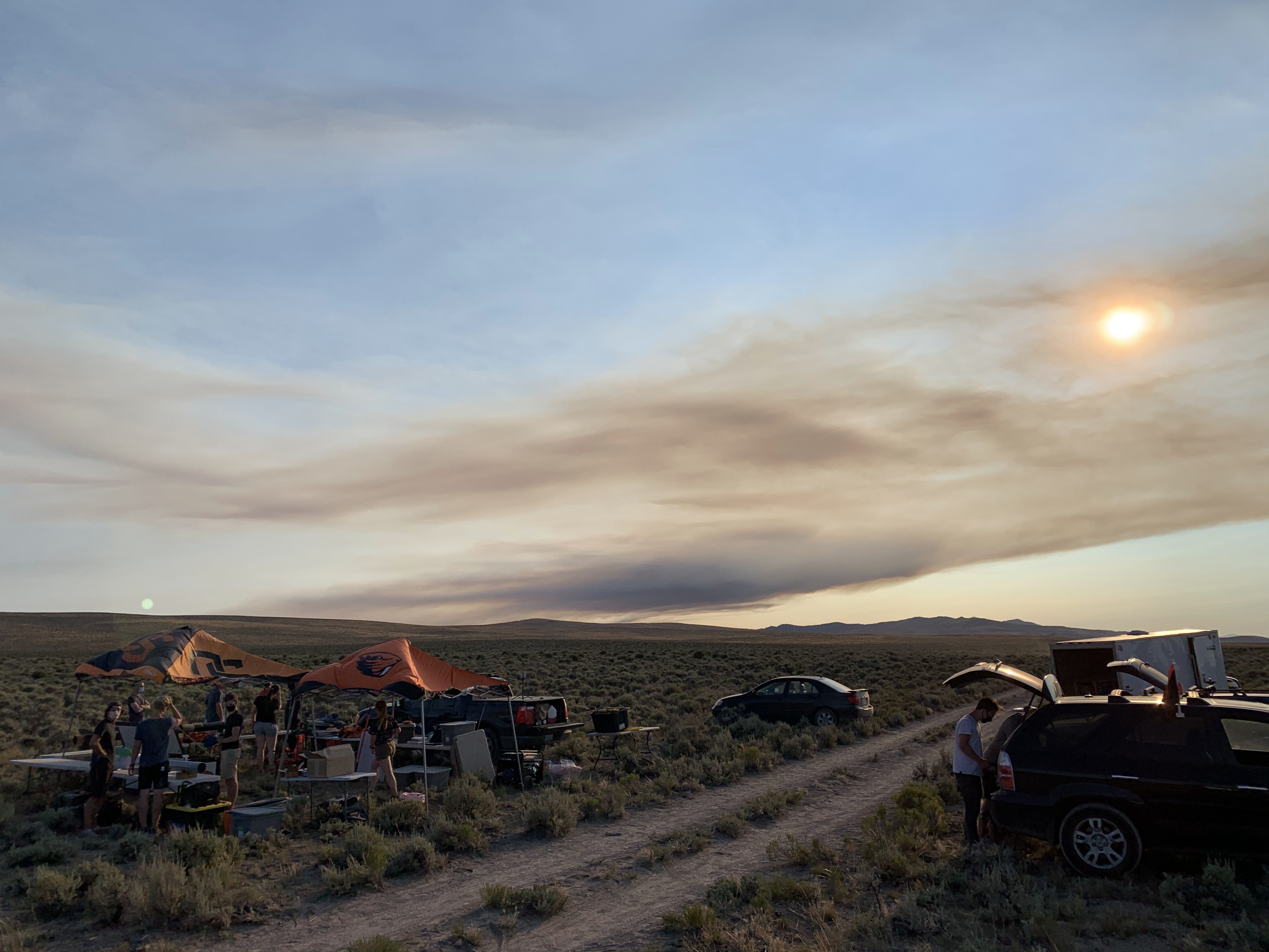
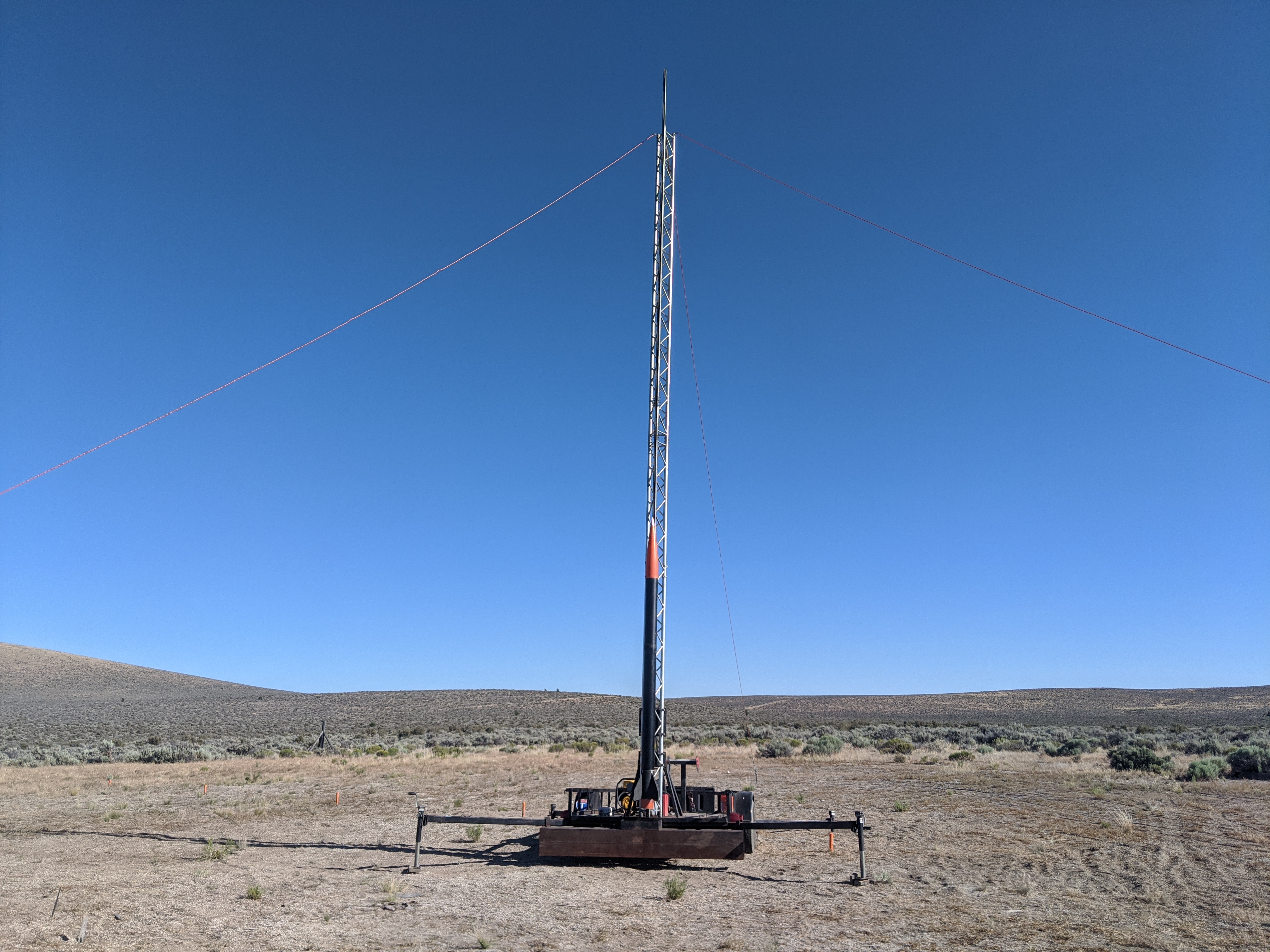
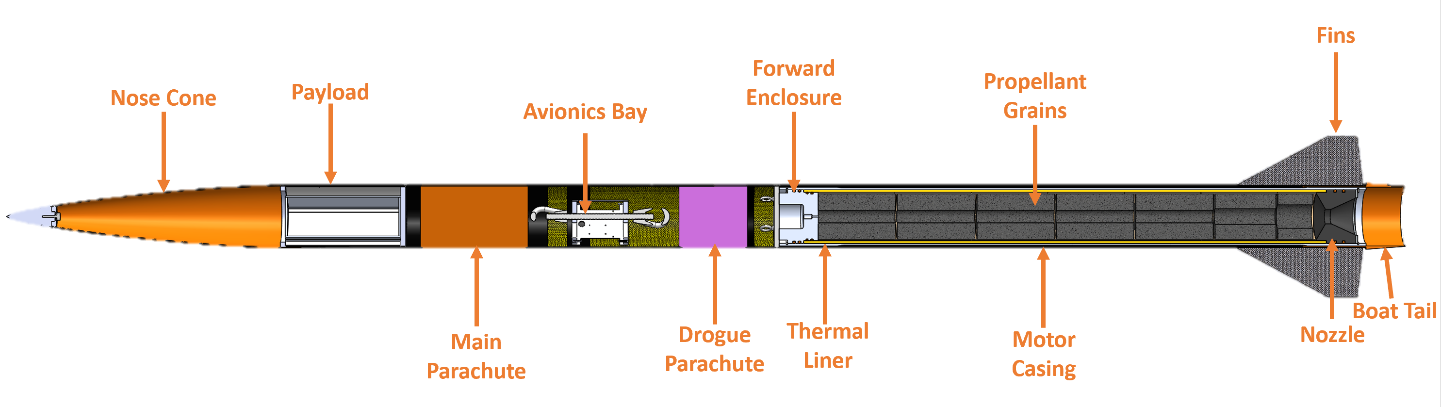
Oregon State University’s (OSU) Experimental Sounding Rocket Association (ESRA) capstone team’s project my senior year was to design, manufacture, and test a level 3 sounding rocket to reach a target altitude of 30,000 ft above ground level (AGL). A sounding rocket, also called a research rocket, is an instrumented rocket designed to take measurements during suborbital flight to perform scientific experiments. The team was driven by 19 ME and 4 ECE undergraduate students. The rocket would have competed against other schools at the Spaceport America Cup, however due to COVID-19 the competition was canceled this year. Because our team was very close to finishing the rocket before the shutdown, we were able to successfully launch the rocket to 29,038ft in the high desert near Brothers, Oregon on July 19th.
The motor propelled the rocket off rail at 10.8g’s burning for 8.3 seconds, reaching a top speed of Mach 1.8.
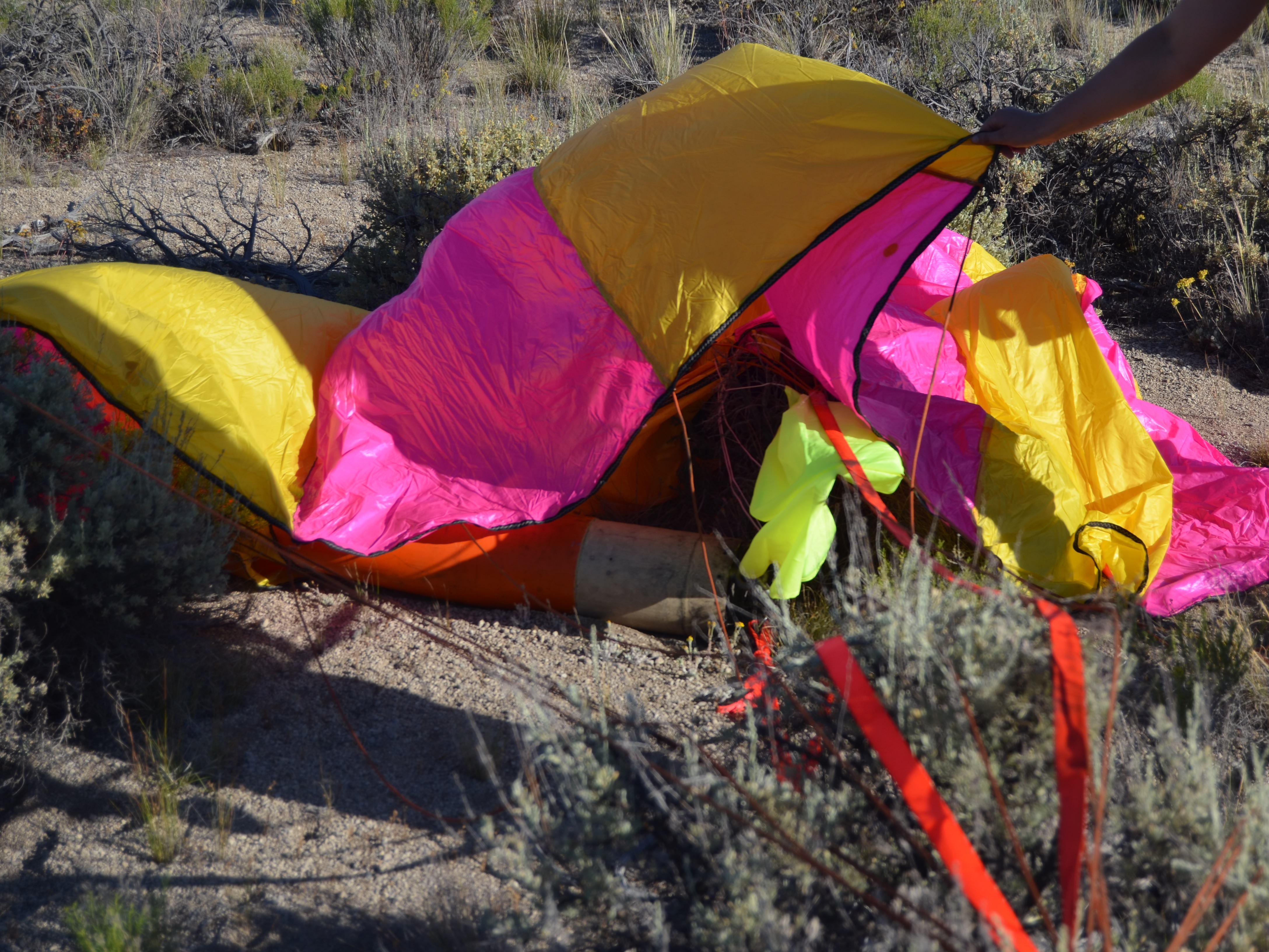
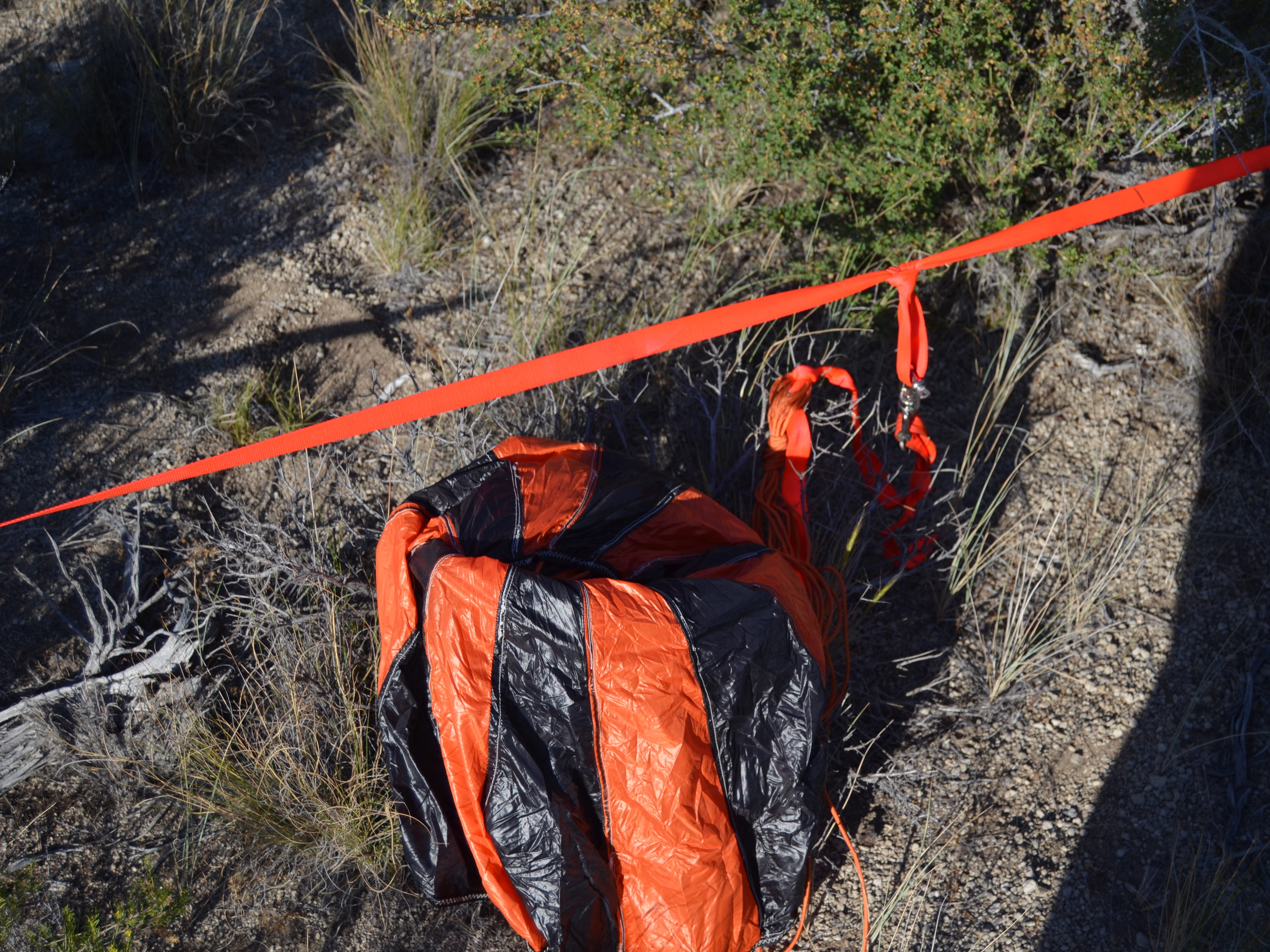
After apogee, the first black powder charge went off, separating the upper and lower body tube deploying the drogue parachute. The rocket then descended at a moderated rate of 108ft/s to an altitude of 1,500ft where the second black powder charge separated the upper body from the nose cone deploying the main parachute, slowing the rocket to a safe speed of 21fps.
Propulsion Overview
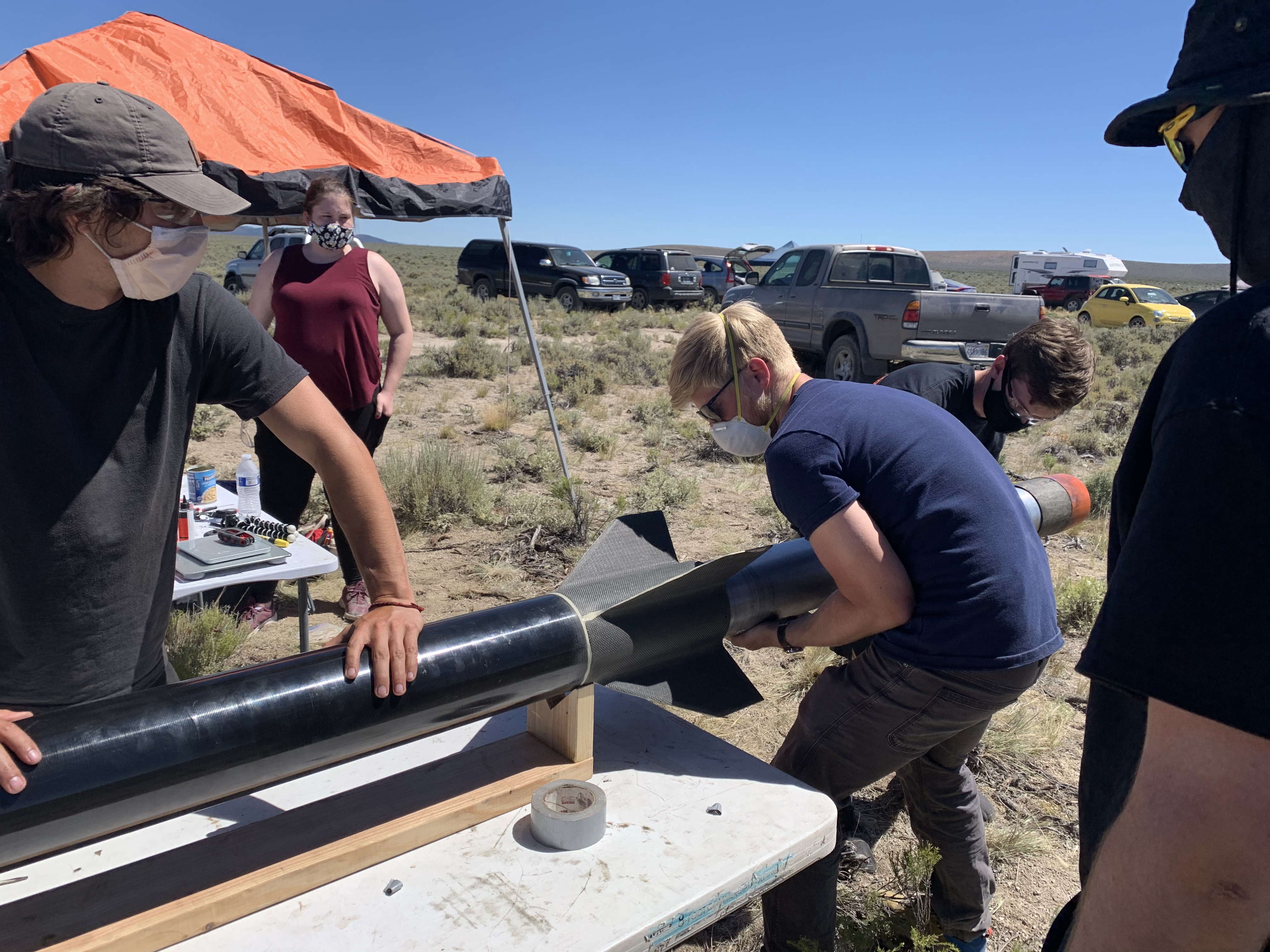
I served in the role of Propulsion Team Lead for 12 months. In that role I discussed and made complex collaborative decisions with our fantastic team in a high stress environment. During my work on ESRA, other sub-teams needed design parameters from propulsion such as the size of the motor, in order to begin working on aspects of their projects. My team and I worked tirelessly during Fall term to finish sub-scale testing and finalize the full-scale motor’s design to allow the rest of the ERSA team to move forward. Additionally, I worked hands-on integrating the rocket, which involved working interdisciplinarily with the avionics, structures, and propulsion teams. After thoroughly testing OSU’s first successful O-class motor, we launched the rocket to an altitude of 29,038ft AGL.
My propulsion sub-team’s mission was to accurately characterize a new propellant in sub-scale, design more robust motor hardware, conduct full-scale static fires before flight, and finally build the flight motor. Propulsion was under pressure to characterize the propellant and determine the size of the motor as quickly as possible so that other sub-teams like aero & recovery and structures & integration could move forward with stages in their projects. We planned to finish sub-scale and decide on the motor size before the end of Fall term. This was an ambitious goal, as most propulsion teams take two years for their projects. While this was a fast-paced project, we also kept in mind how easy it is to make little mistakes that can lead to catastrophic motor failures. Our team talked through almost every decision as a group before carefully moving forward.
Team roles
-
Cole
As the team lead my main responsibilities included managing sub-team projects, coordinating with other sub-teams and superiors, and facilitating a healthy and productive work dynamic within the sub-team. My leadership style was to make decisions as a group and trust individuals in their areas of expertise, but ultimately I made final decisions. I also served as the point of contact for team sponsors and advisors. My primary individual responsibility was designing, building, calibrating, and testing the data acquisition system for static fires. You can learn more about that project here! -
Tom
Was primarily responsible for the sub-team’s nozzles. This involved using BurnSim to determine optimal nozzle throat diameters and manufacturing these nozzles out of graphite. Tom was also one of the Co-ESRA team leads and coordinated operations and test logistics. He handled funding, ordering, sponsorships, team integration checklists, and launching in Brothers. -
Michael
Served as the sub-team part data management (PDM) lead. This involved: organizing team data, integrating sub-team CAD parts with other sub-teams. He took point on the post processing on static fire data and characterizing the propellant. He also assisted me on the DAQ. -
Caspar
Oversaw propellant mixing. His job was to understand the chemical formulas and processes required to produce each formulation and simulate each formulation in Propep. He acted as the middle-man between Jim Baker - the chemistry mentor - and the sub-team. Caspar was also co-responsible for the CAD work required for the nozzle, thermal liner, grains, and casting tube and fully responsible for turning in group projects. He took imitative on designing and building the sub-scale and full-scale test stands.
Characterizing Propellant
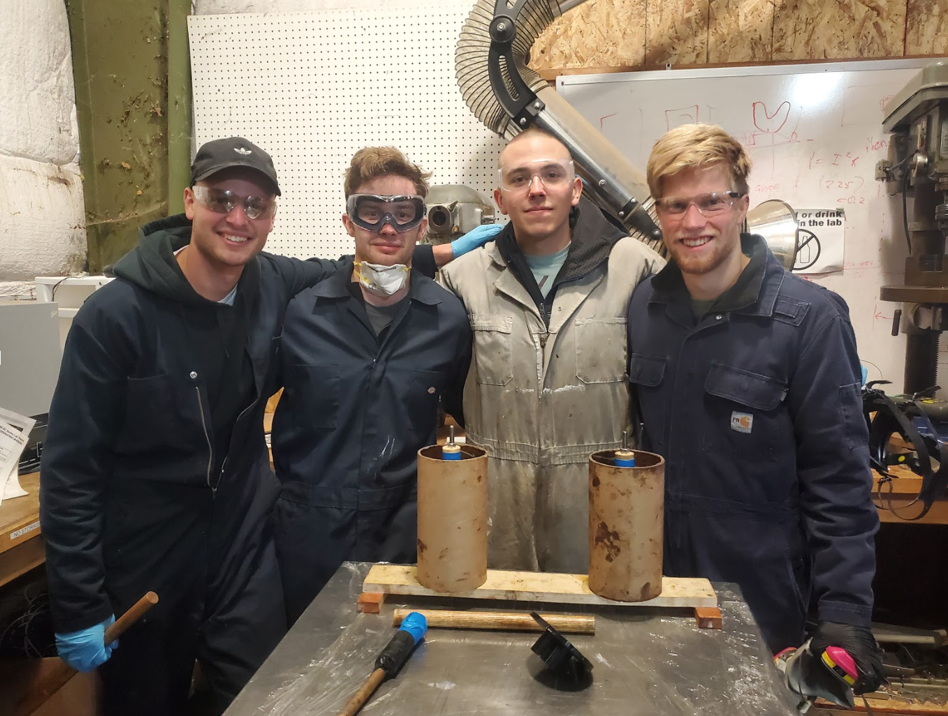
Characterization is the process of determining the relationship between chamber pressure and burn rate which was done empirically through sub-scale static fires. We mixed many miniature motors and fired them with varying nozzle throats. Mixing a batch of propellant takes about 5 hours and full-scale motor requires 3 batches. In order for our models to be accurate, it was really important that each batch was consistent. Ingredients were measured out on a lab scale and mixed using a commercial kitchen mixer.
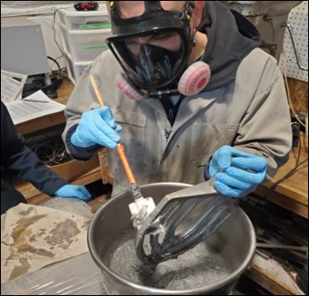
The propellant was then packed into cardboard casting tubes to form sub-scale grains.
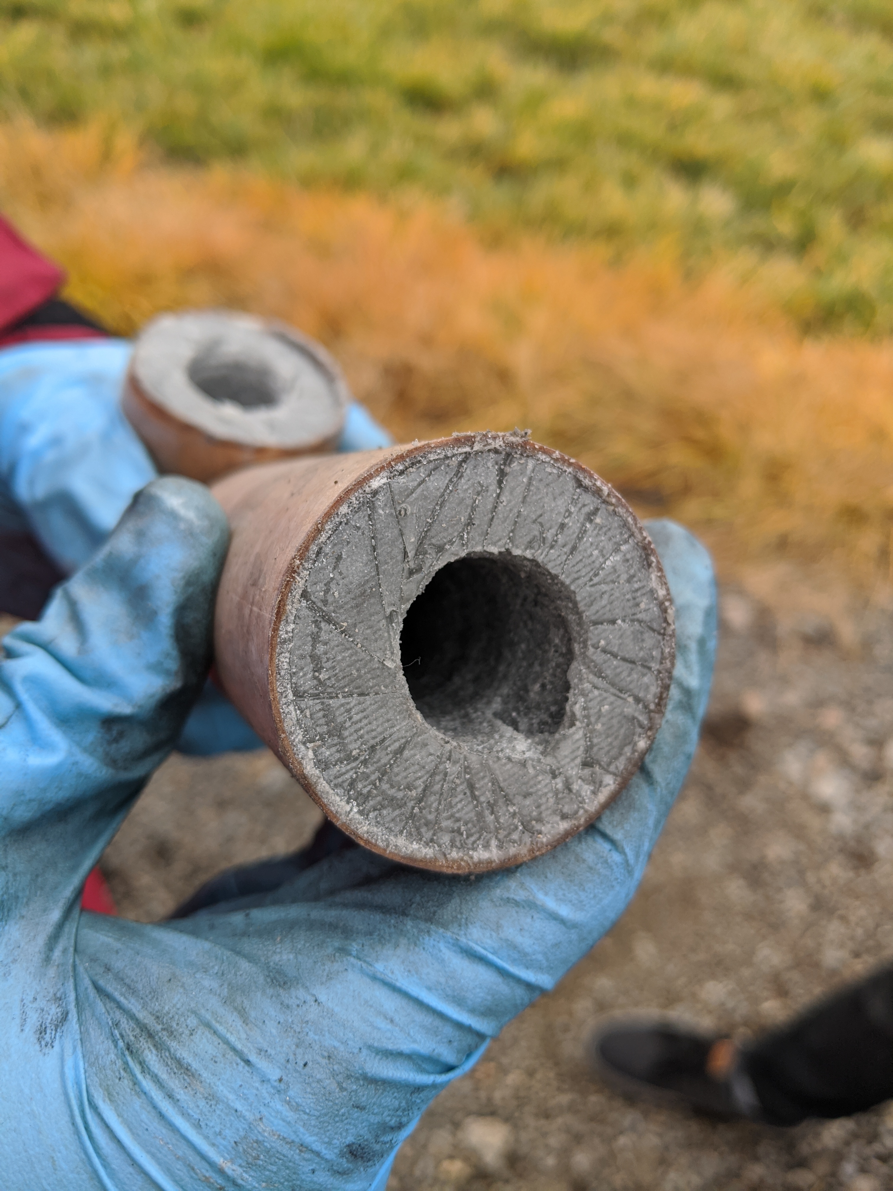
Earlier in the year we had issues with low density propellant even with vacuum pumping. This lowers performance, but it can also become problematic if the propellant is porous because it can cause an over pressurization from an expanding gas pocket. Our solution was to clamp the propellant in fixtures while it cured. This resulted in densities >95% theoretical!
After sub-scale mixing we began static fire testing. The propellant burns on the uninhibited surfaces of the grains. For a bates grain configuration which is what we used, that would be the inner core and ends of the grains.
The burn rate is proportional to the chamber pressure shown in equation 1.
r=aPn.
Equation 1
Where:
r = Burn rate
P = Chamber pressure
a and n are unknown constants.
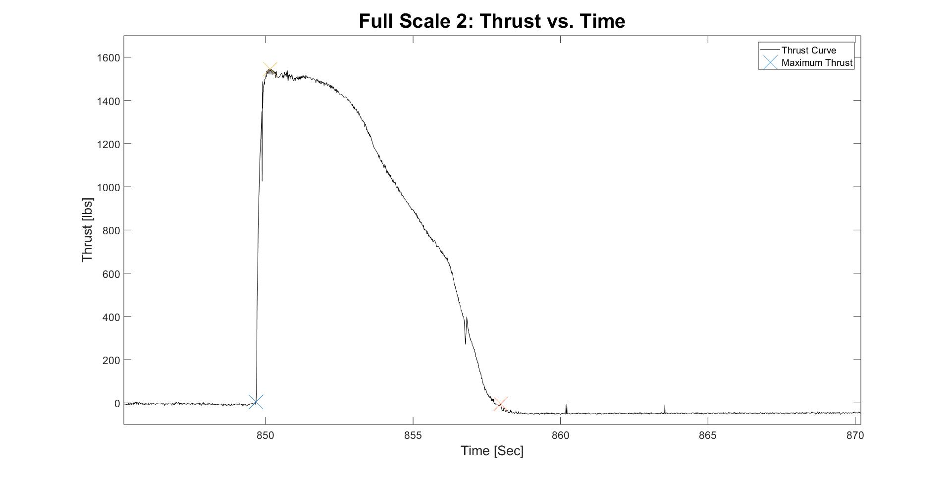
From the static fires, we calculate burn rate using the burn time and grain geometry.
This is a video of one of the static fires.
At one point during the term, the propulsion lab where we previously conducted sub-scale was shut down to make room for a grad-student project. Not to be deterred, we instead built a new test stand and conducted sub-scale at the Corvallis airport. This was the test stand we built.
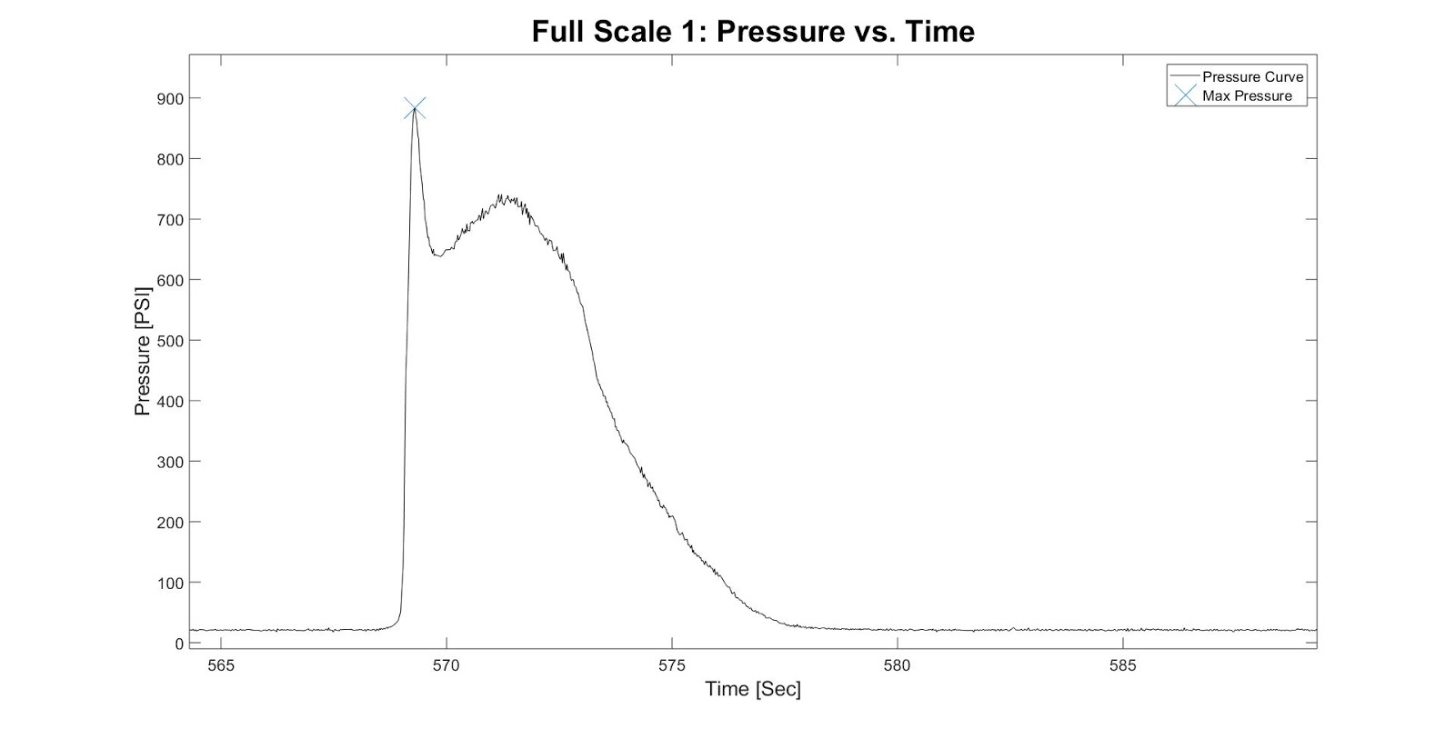
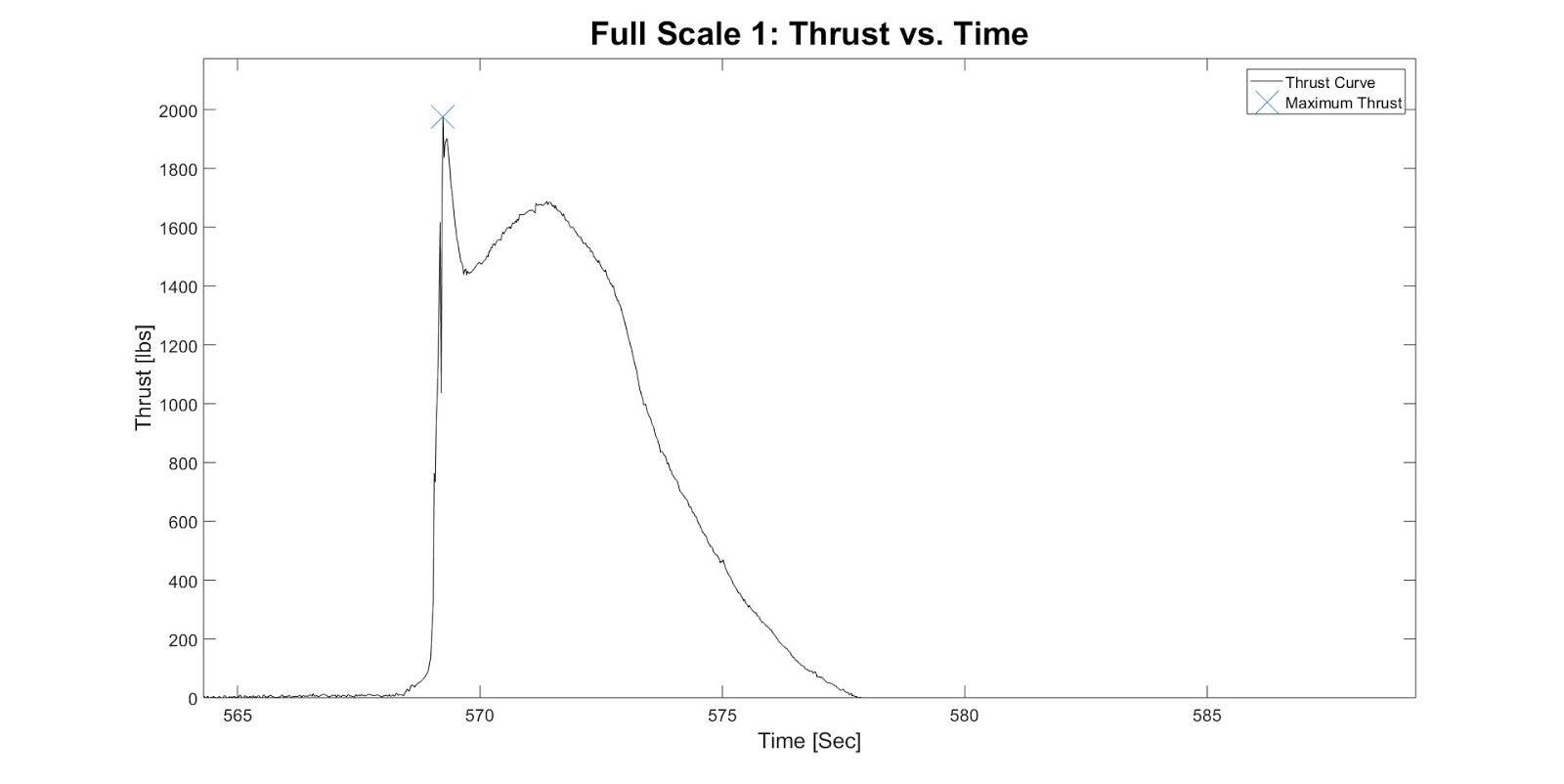
The motor inside the testing tube was constrained axially by three centering rings. We recorded pressure and thrust data. The combustion chamber was connected to a pressure transducer by an air-filled copper tube. The motor could not simply sit right on the load-cell because the pressure tube was in the way, so an adapter sat on the circumference of the motor and transferred the thrust to the load cell. You can see the copper tube come out of a cutaway in the adapter.
We recorded the pressure and burn rate of each motor and used that data to solve for the a and n values shown in equation (1).
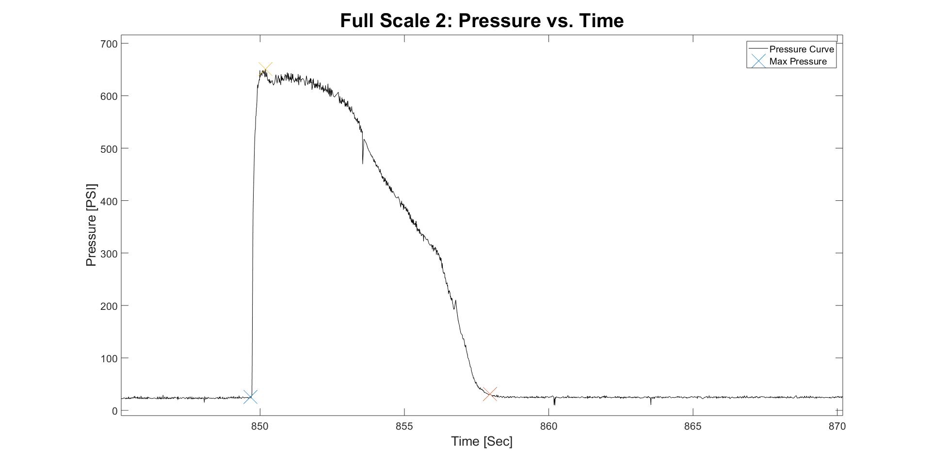
We also calculated our characteristic velocity c* from the pressure curve shown by equation 2.
c∗=Atmp∫P(t)dt
Equation 2
Where:
At = nozzle throat area
mp = propellant mass
P(t) = pressure with respect to time
With this information we were able to predict the chamber pressure of the full-scale motor based the a, n and c* values as well as the propellant mass, geometry, density, and throat diameter shown by equation 3.
P=knρrc∗
Equation 3
Where:
kn=AbAt
Ab = Burning surface area
One of the tools we used to simulate the performance of the motor based on these parameters is BurnSim.
This allowed us to design the full-scale nozzle safely for the performance we required.
Prevent thermal failure
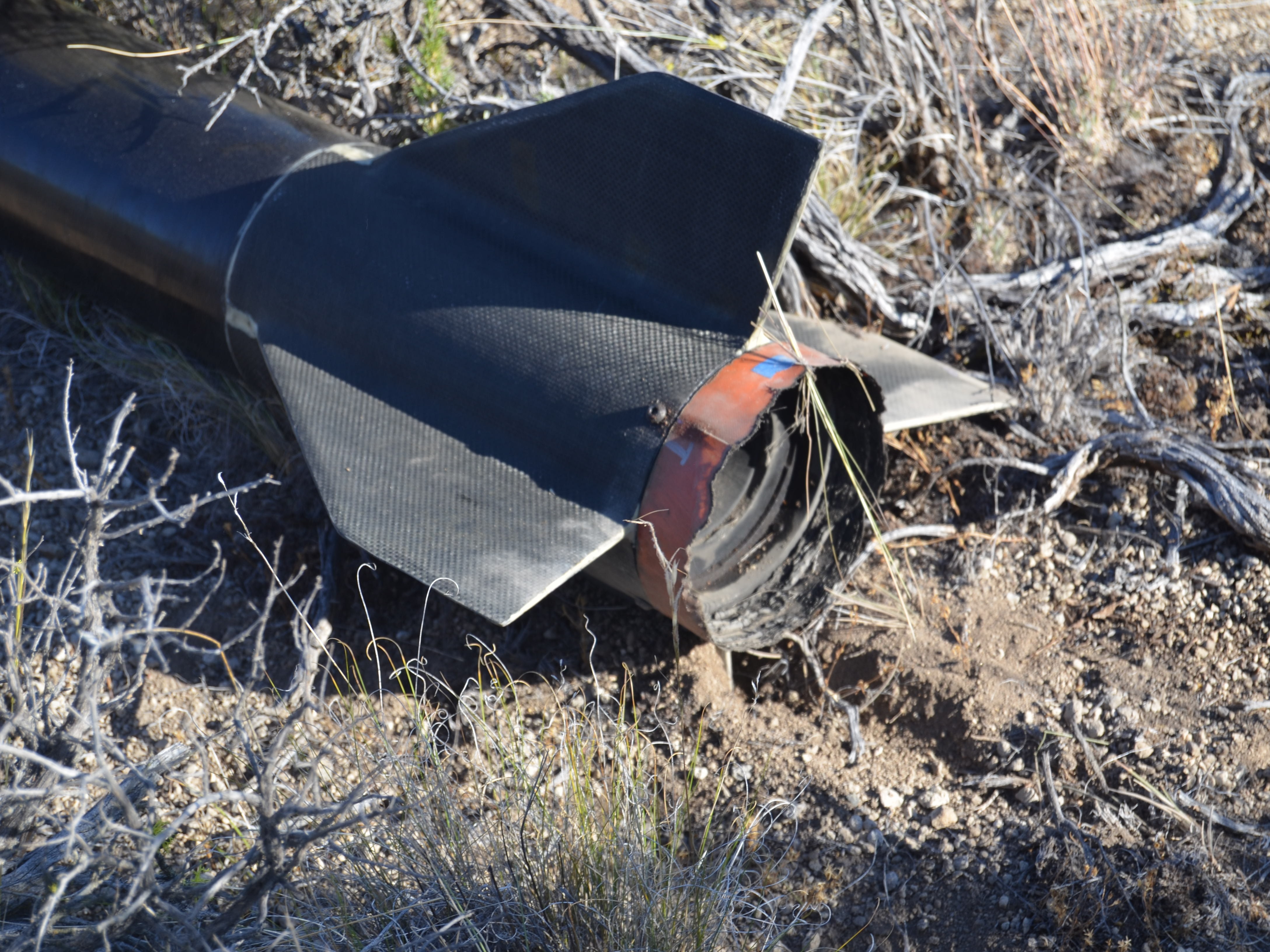
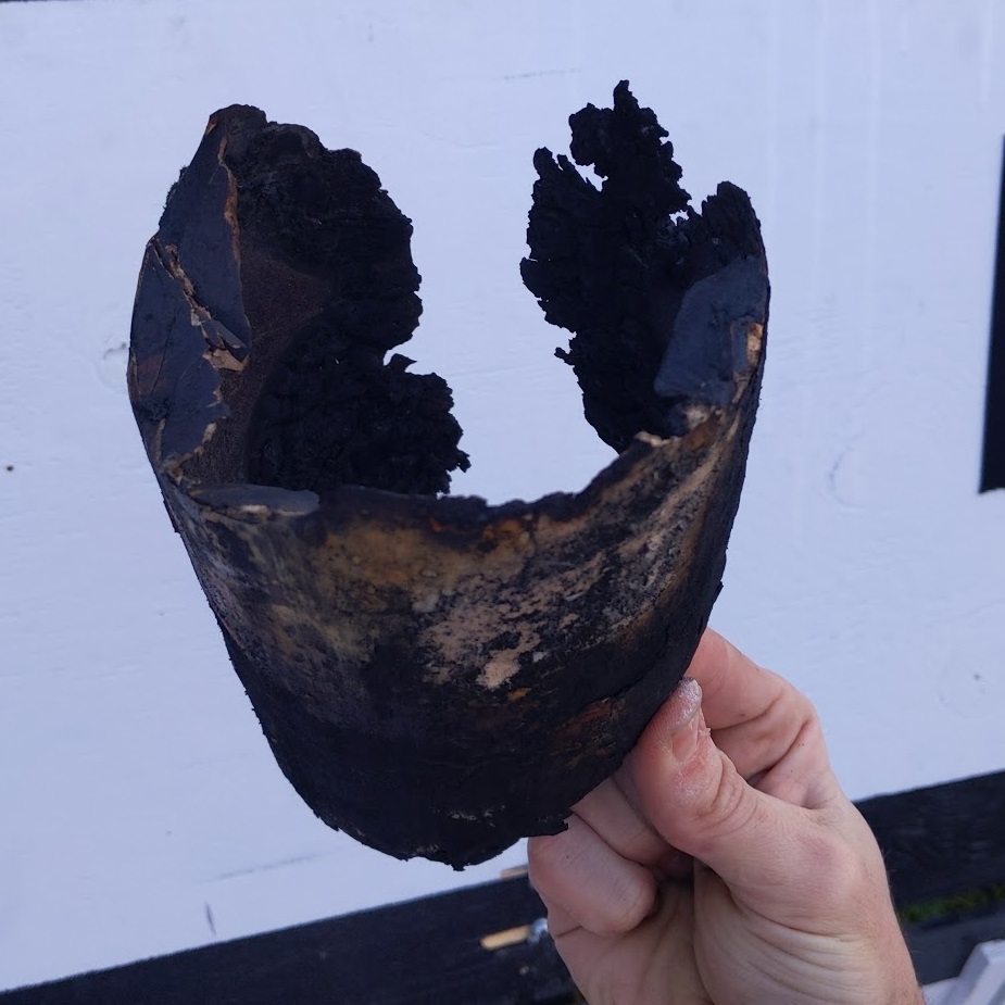
Propulsion this year was particularly challenging, because the previous two years’ motors had experienced thermal failures. The aim of our year was to design a robust and reliable motor and allow future years to optimize for weight savings later on. The pictures below showcase a motor that had suffered this fate.
Forward enclosure and upper motor tube after thermal failure.
Lower body of motor after thermal failure.
A thermal failure occurs when the motor assembly’s temperature gets too high, lowering the yield strength of the material below the hoop stress of the combustion pressure causing the pressure vessel to rupture. It is suspected that in previous years the motor tube and forward enclosure overheated from hot gasses circulating through the forward end of the combustion chamber, past the forward enclosure shoulder, between the motor tube and thermal liner, and out between the nozzle shoulder and thermal liner.
Our approach to solve this problem was to seal the area between the thermal liner and forward enclosure shoulder to stop convection. The area between the thermal liner and nozzle shoulder was not sealed to prevent the thermal liner from becoming a pressure vessel.
In addition to the seal, we used a fiberglass thermal liner as opposed to a phenolic liner for better insulation.
We designed the nozzle’s throat based on the exact densities of the propellant batch and machined the graphite nozzle in-house.
Full-scale static fires
It was during this mix that we took back all our complaints about how long mixing took during sub-scale.
The first full-scale static was the first test for the new motor hardware design. This was also the first static fire ever at OSU where thermal data was recorded. This was exciting to see because up until this point, even if the fire was successful, it wouldn't tell us if we were close to any dangerous temperatures.
The motor tube reached temperatures around 80F near the center and forward enclosure, and about 180F near the nozzle end. However, this was many minutes after the burn from conduction from the nozzle, and motor tube temperature only rose a few degrees Fahrenheit during the burn. The new liner and seals were clearly working.
There were a few issues with the first burn. The first was a bit of erosive burning at the start.
Next, the ignition was very slow (about 10 seconds).
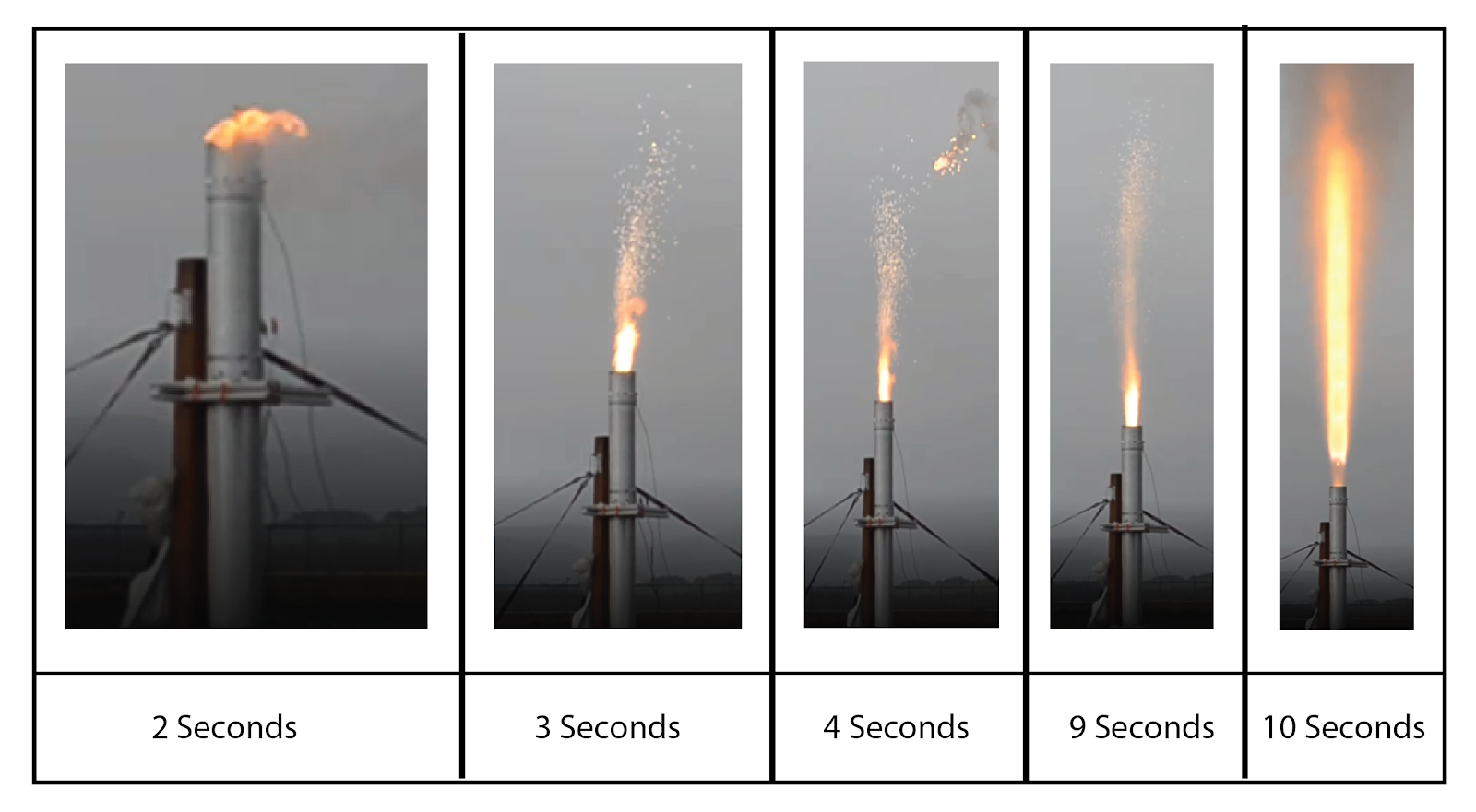
There were also a couple chuffs from spacers used between grain ends and bits of casting tubes.
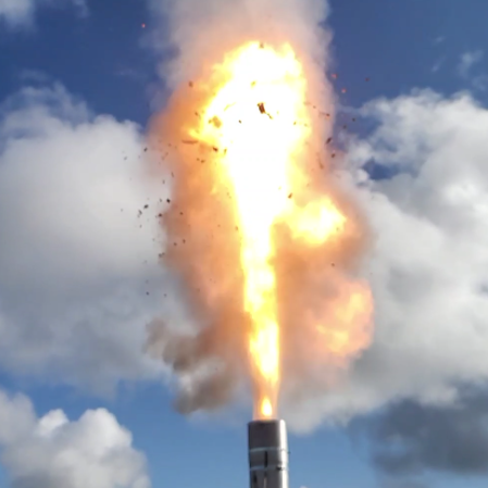
For the second static fire, we solved these problems by making a new igniter, this time using thin strips of a blue lightning hobby motor, adding a shoulder to the casting tubes to remove the need for spacers, using more epoxy on the grains to prevent casting tube bits from dislodging, and opening up the core diameter of the aft most grain to prevent erosive burning.
The result was a very smooth burn with a quick startup and no chuffing. This was the motor configuration to fly on.