Tabletop CNC Mill
I thought it would be fun to build a 3-axis tabletop CNC mill. I wanted to make it mostly out of aluminum bar stock so I would machine the parts myself using the machine shop at school. I had a seen a lot of hobby mills online constructed of wood, but I wanted it to be rigid enough to be able to machine aluminum. I mocked up a design and pitched the idea to a club at OSU called Inventor’s Enterprise which helps make it possible for students to execute their project ideas. They thought the idea was worthwhile, and they helped fund the project with a $265 grant, which was enough to pay for the linear bearings. Luckily, I had also saved some money from my MECOP internship at Daimler to pay for the rest of it.
Overall Design
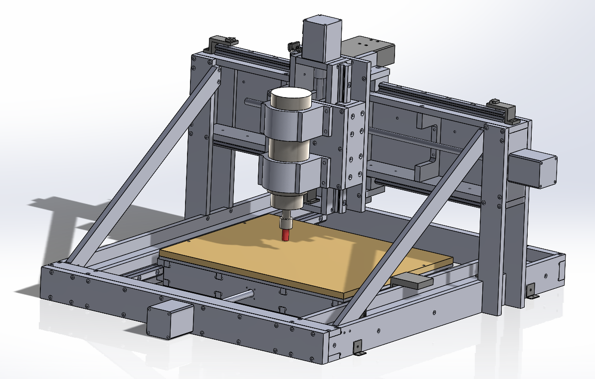
The first thing I decided when designing the mill was whether it was going to be a mobile gantry with a stationary bed, or a stationary gantry with a mobile bed. For small machines, the gantry is usually larger than the bed, so I made the gantry stationary.
The bed slides inside of the gantry on linear guide rails each mounted to an I-beam. A stepper motor mounts to the C-beam on the front to drive the X axis motion.
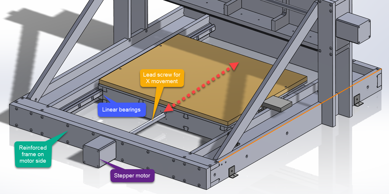
The stepper motor is coupled to a lead screw that is threaded through a lead nut mounted on the inside of the bed. Rotating the lead screw moves the bed along the linear bearings. The top of the bed has a disposable MDF board for mounting parts to.
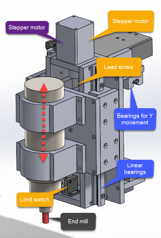
On top of the gantry is a spindle mount assembly that controls the Y and Z axis motion. The assembly slides along the rails on the top and bottom of the gantry which resembles a C-beam.
The stepper motor on the side drives a lead screw to control the Y axis motion. The spindle mount assembly has a lead nut that travels within the channel of the C-beam.
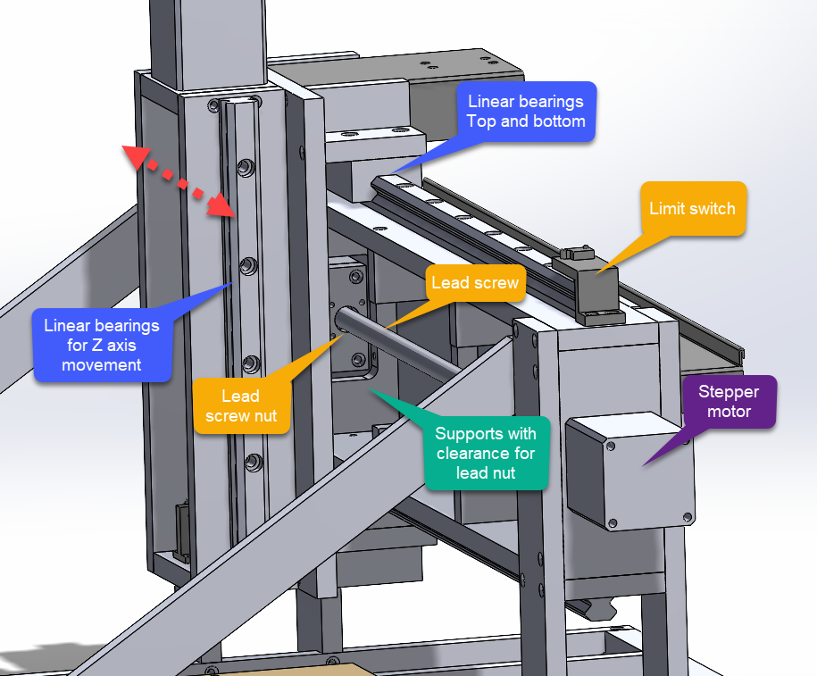
The Z axis motion occurs on the front of the spindle mount assembly. This was one of the more complex components of the mill because it accommodates two axes of motion. The stepper motor on the top drives the spindle up and down.
It is also complex because the Z axis motor is the only stepper motor that is not stationary. Therefore, the wiring for the motor needed to be routed such that it could move without getting caught on something. Additionally, the coolant line for the motor needed to be routed the same way. This is where cable tracks come in.
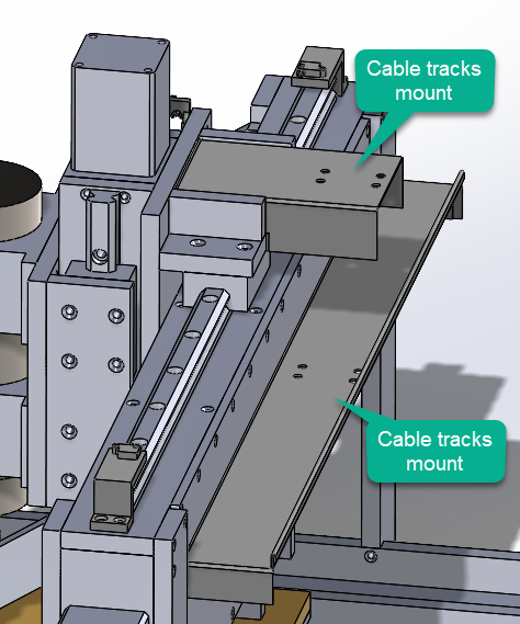
I did not model the cable tracks themselves, but the back of the gantry and top of the spindle mount assembly have sheet metal brackets to mount the cable tracks to.
This video shows a model of the machine’s movement.
Designing the Frame
When I designed the frame of the machine, I first began by estimating the load from machining the toughest job. Once I had solved for the force, I used that number to ensure the deflection of the machine would be small enough to deliver the tolerances I wanted to hit.
Calculating Cutting Force
I wanted to build a 3 axis CNC mill that would be able to machine aluminum 6061 within +/-0.001in at the maximum feed of a 1/2in solid carbide 2 fluke endmill at a 0.100in depth of cut. I calculated the expected cutting force using the equation below.
\(F_t = {\sigma}_{ut} A_c Z_c C_m C_f\)
Where:
\({\sigma}_{ut}\) = Ultimate tensile strength of the material
\(A_c\) = cross sectional area of an uncut chip
\(Z_c\) = number of teeth cutting at once
\(C_m\) = machinability factor
\(C_w\) = tool wear factor
For aluminum 6061:
\({\sigma}_{ut}\) = 45,000psi
\(A_c = a_p f\)
Where:
\(A_p\) = axial depth of cut = 0.100in
\(f\) = feed per tooth
For a solid carbide ½” endmill cutting aluminum:
\(f\) = 0.0022in
\(A_c = (0.0022in)(0.100in) = 0.00022{in}^2\)
For a two fluke endmill only 1 fluke will be engaged at once, therefore:
\(Z_c = 1\)
The machinability factor depends on the material and the width of cut to tool diameter ratio. For a worst-case calculation, WOC/D = 1.
Using a lookup table: \(C_m = 1.1\)
The tool wear factor for a sharp tool is 1.0. However, for longer operation, it increases. I assumed heavy-duty wear to be conservative.
\(C_w = 1.3\)
With the following quantities know, the tangential cutting force can be solved for.
\(F_t = (45,000psi)(0.00022{in}^2)(1)(1.1)(1.3) = 14.2 lbf\)
I used this number to calculate the maximum deflection of the bed, gantry, and spindle assembly in x, y, and z directions and sized the supports to have a maximum deflection within the target tolerance. The z component of the force is going to be smaller than the x and y, however I estimated it to be the same to be conservative.
Calculating Deflection
To ensure that the mill was within tolerance, I calculated the X, Y, and Z axis deflection of most important components. I am only going to show some of the calculations because there are a lot, but I will start with the X deflection of the base.
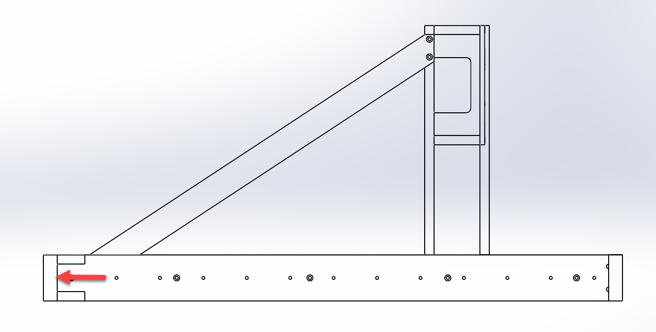
X axis deflection
As the spindle exerts a resistive cutting force the in X-direction, that load is transferred through the lead screw to the front of the frame. The picture below shows a cross section of the beam.
For a pinned beam with a point load applied at the center:
\(\nu_{max} = \frac{PL^3}{48EI}\)
Where:
L = 27in
P = 14.2lbf
E = 10,000ksi
I = 1.4238 \(){in}^4\)
Therefore:
\(\nu_{max} = \frac{(14.2lbf)(27in)^3}{48(10,000,000psi)(1.4238 in^4)} = 0.000409in\)
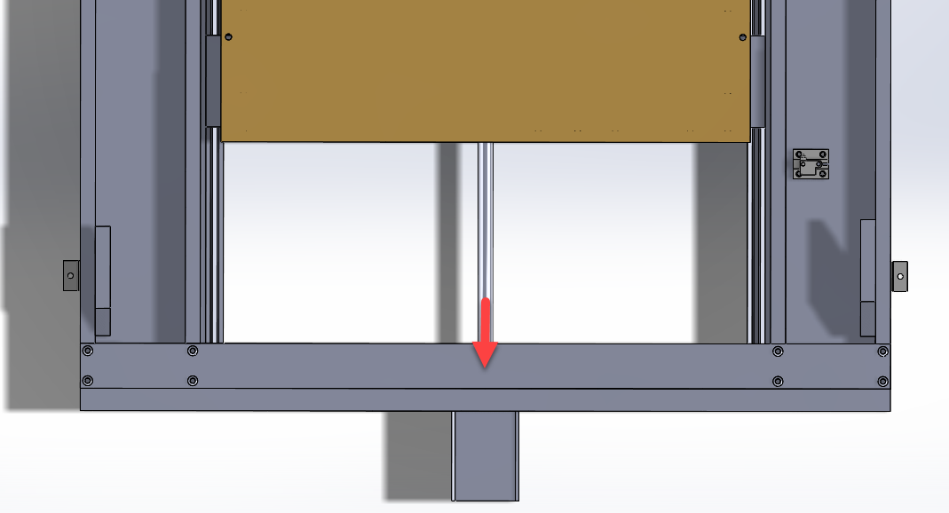
Y axis deflection
I then calculated the deflection in the base in the Y axis.
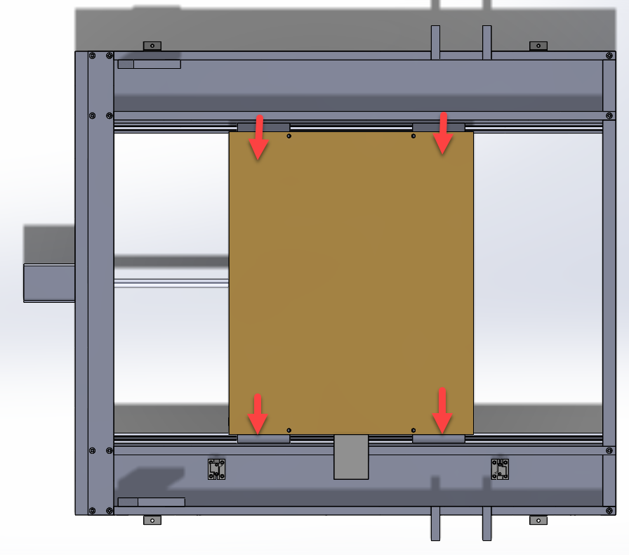
For this calculation I am looking at the beam deflection of the two I-beams that the linear rails mount to.

For this problem, the sides are symmetrical, so the problem can be modeled as a single beam where each arrow exerts 1/4th of the cutting force.

I solved for the deflection by integrating the moment equation twice until and dividing over EI.
\(M = EI\frac{d^2\nu}{dx^2}\)
The two boundary conditions known are that \(\nu\) = 0 at x = 0 and x = L, and \(d\nu\) = 0 at x = L/2.
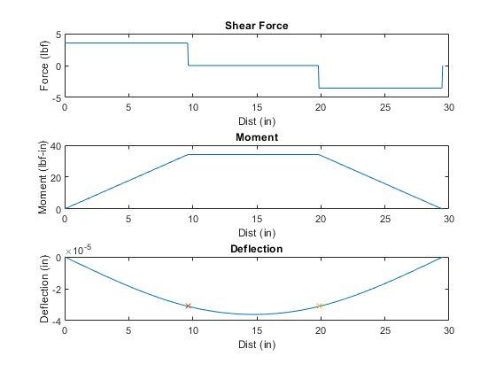
This time we are not looking for the maximum deflection, because we are only concerned with the deflection of the beam at the bearings, that is x = a and x = L-a.
The deflection at these points are -0.000031in for both.
Linear Motion
The bed and spindle slide and linear bearings and the assemblies are driven by ACME lead screws coupled to stepper motors. I designed the mill to be able to move 0.0005in per step without micro-stepping. The lead screws I found had 10 threads per inch. I selected a motor with 200 steps per revolution for a movement of 0.0005in per step.
\(\frac{dist}{step} = \frac{l \theta_{step}}{360^{\circ}}\)
Where:
N = Threads per inch
\(\frac{dist}{step} = \frac{\theta_{step}}{N360^{\circ}} = 0.0005\frac{in}{rev}\)
Spindle
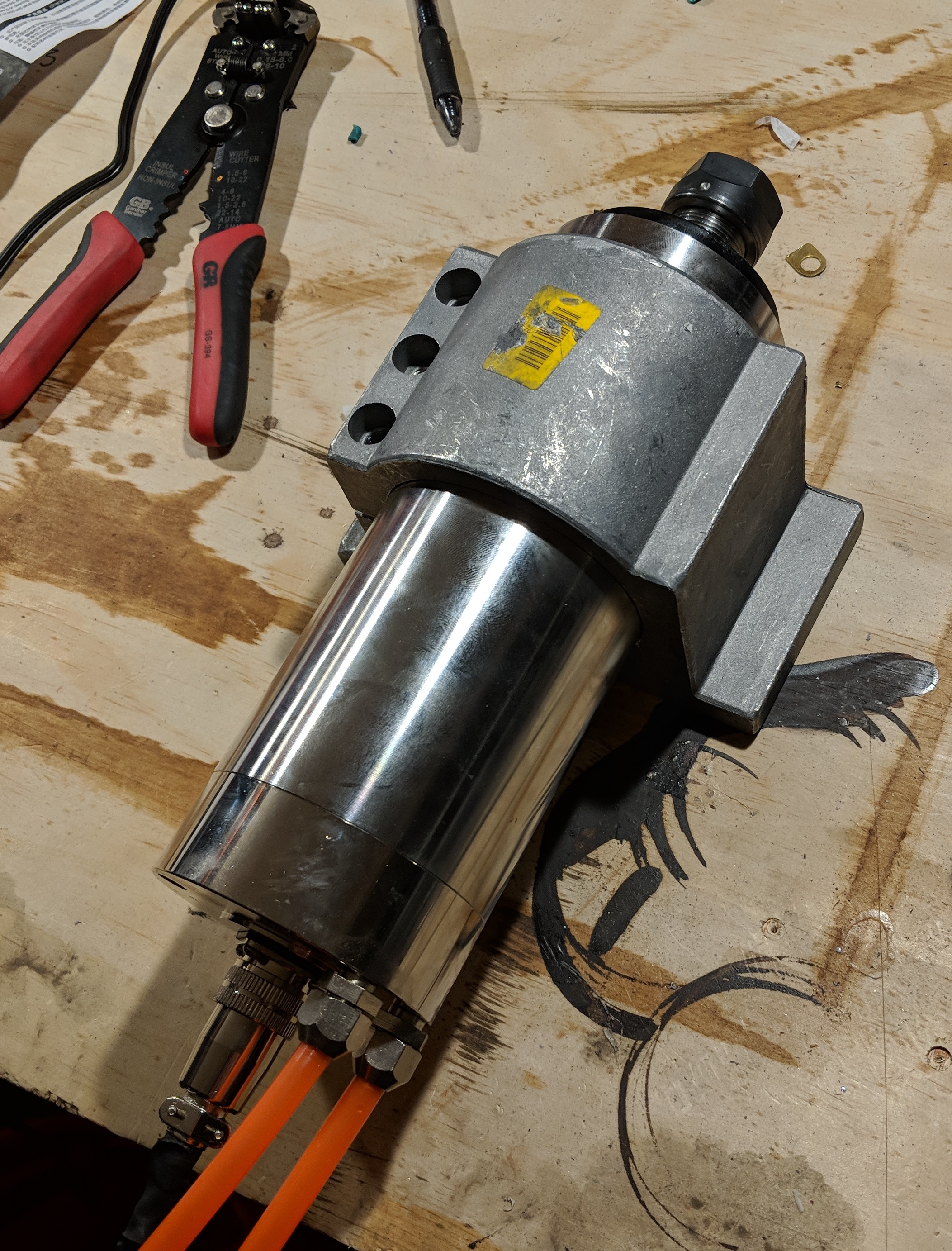
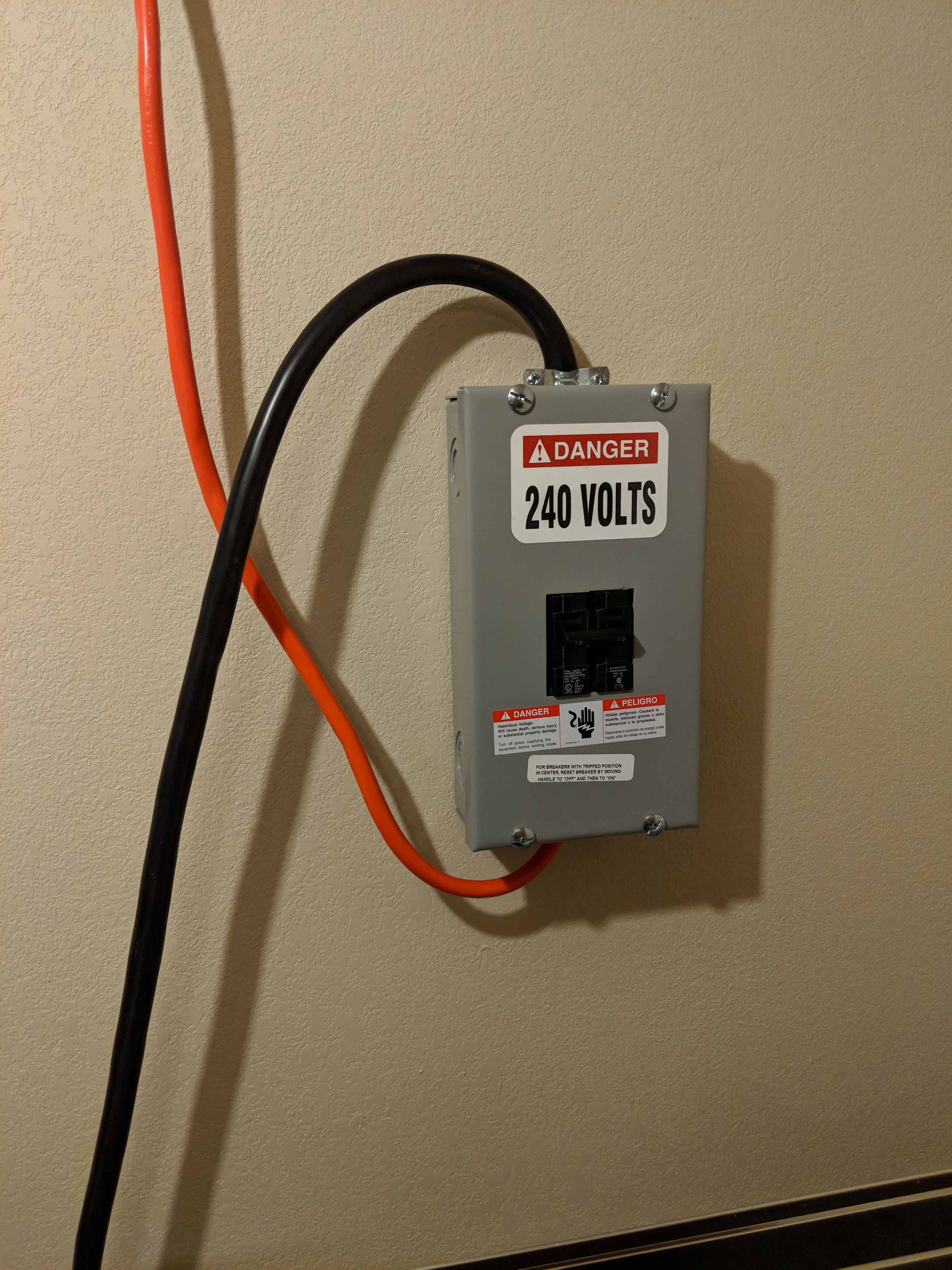
I wanted the machine to be quiet, so I went with a liquid cooled spindle. It uses a fountain pump that circulates coolant from a five gallon bucket. The spindle is powered by a variable frequency drive which is runs on 220VAC. I had to unplug the drier to power it. Luckily my roommates didn’t mind. I installed a 15A breaker just to be safe.
Electronics
I found an old PC and loaded an operating system called Linux CNC which handles the CAM and g-code to run the machine.
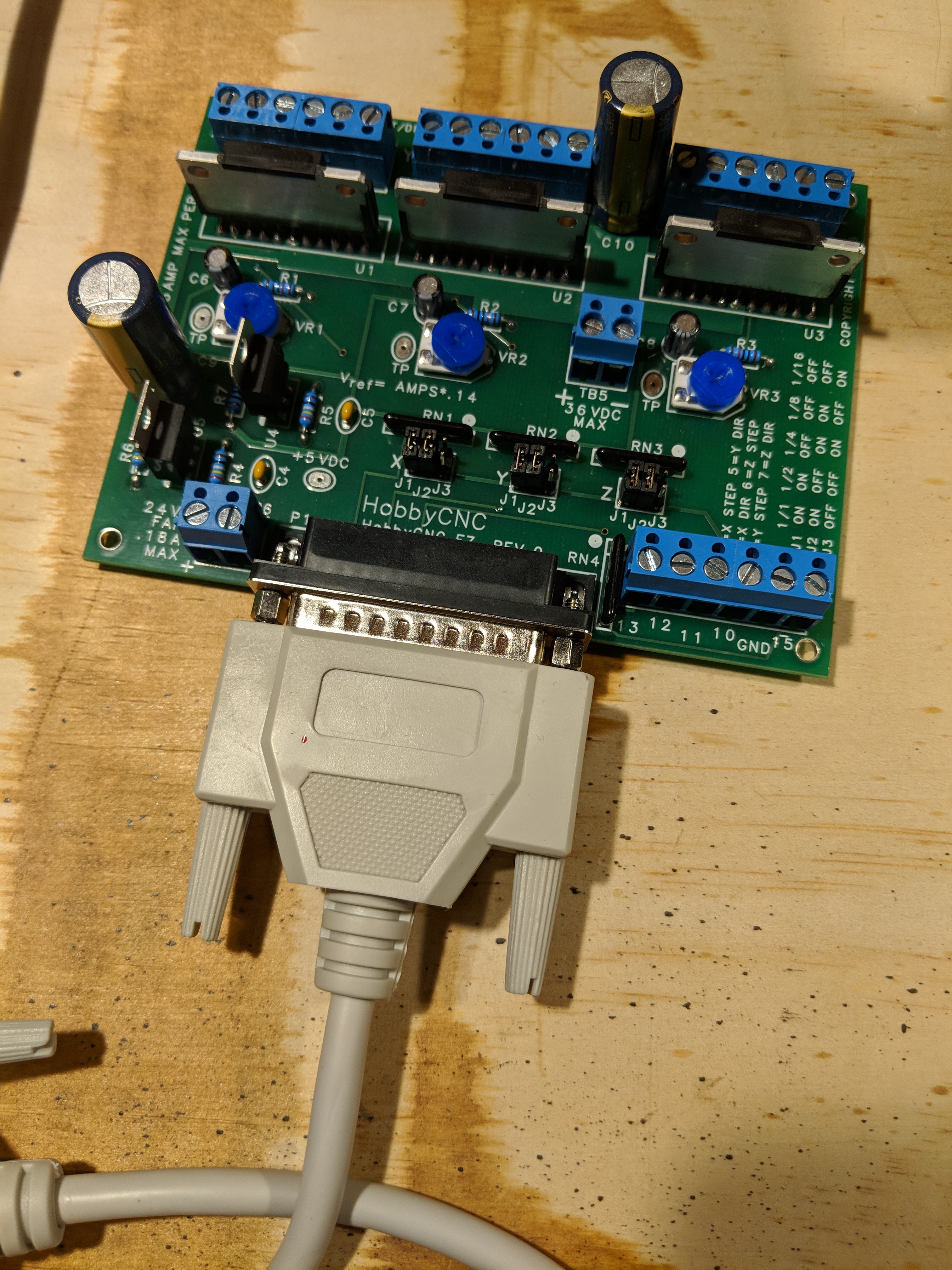
I used a 3-axis stepper driver board called EZ-board to drive the motors. The driver board connects to the PC which allowed me to control the motors from the computer.
Current Progress
The electronics are working to control the spindle, stepper motors, and limit switches. The drawings are finished, and I am in the process of machining.
Stay tuned for more as the project progresses!